Wednesday 14 December 2016

Working Santa's elves in Lapland, Christmas 2016

Every week I produce the HF propagation report for the RSGB's GB2RS news. This week I thought I would do something a little different. If you have children or grandchildren they might find it interesting. I worked them on 20m SSB on the 14th and they were LOUD! Here is the report:

----------------------------------------

This week we have a slightly different approach to the HF propagation news. We want to help you and your family contact Santa's elves in Lapland, Finland.

The station Oscar Foxtrot Nine X-ray (OF9X) is once again on the air this Christmas from Santa Claus land in the Arctic Circle.

Twelve elves are operating OF9X (that is, “Old-Father-Nine-Christmas”) from the city of Oulu in Finland for the entire month of December

To work the elves at OF9X, the best starting point is the DX cluster or reverse beacon network to see where they are operating. They have been spotted on many bands and modes over the past week.

The HF predictions suggest seventeen or twenty metres (18MHz or 14MHz) both give a good possibility of a contact with a probability of greater than 90% during the hours of daylight. Even 15m may be possible around midday.

Forty metres (7MHz) should also give a high probability for the whole 24 hours, while 80m and 160m may also be open during the hours of darkness in the UK.

But get in quick, NOAA is predicting unsettled geomagnetic conditions from December 19th to the 23rd due to a recurrent coronal hole.

Wednesday 30 November 2016

Quarter wave verticals for HF

The radiation pattern for a quarter wave vertical.
I had an email from a radio amateur who was struggling to work DX after putting up a very off centre fed dipole cut for 40m and fed with open wire feeder.

This is probably not the best way to go about it as the off centre feed can cause an imbalance and create RFI problems.

I suggested a better DX antenna might be a quarter wave vertical cut for the band in question and fed against a decent ground plane. But what is a decent ground plane?

Rudy Severns N6LF has done extensive research on this, but his conclusion was that you really need as many radials on the ground as possible. Up to 120 is optimal, but you will notice an improvement as you add more and more with perhaps 16-32 being the minimum for good performance.

Don't be misled by your SWR meter as a single earth stake may give you a low SWR, but what you are seeing may be the effect of ground losses.

A quarter wave vertical should have a theoretical impedance of about 35-36 Ohms, so if you have a 1:1 match you are seeing 35 Ohms, plus 15 Ohms of ground losses.

As you add more and more radials the SWR may INCREASE. This shows it is starting to get closer to the optimum 35 Ohms.

The goal is to keep on adding ground radials until the SWR stops changing. Then the vertical is working about as good as it can.

Rudy found that once you get above 32 ground radials the improvements start to get more subtle and increasingly minimal.

But how long should the radials be be? A quarter wave radial laying on the ground is detuned so a true quarter wave is no longer a resonant radial, although it is a good overall compromise.

So the golden rule is that for a given amount of wire more shorter radials are better than fewer longer ones. This helps to collect the ground currents around the base of the antenna and improves the antenna's efficiency.

If it is a multiband vertical then the compromise is to make them as long as the antenna is high. If it is a monoband antenna then perhaps a quarter wave is best, although eight "eighth wave" radials might work better than four quarter waves (if on the ground).

In tests though you will find that two resonant elevated radials fitted so that they are at 180 degrees to each other may work as well as eight or so random radials on the ground. Rudy suggests that more resonant quarter wave elevated radials may be better still, but its starts to get a bit unwieldy.

A few years ago my club used a quarter wave vertical cut for 40m and fed against two elevated quarter wave radials and it worked very well. For contacts out to Germany from the UK there was little in it compared with a horizontal half-wave dipole at about 40 feet. Closer-in contacts were louder on the half wave horizontal dipole due to the different radiation pattern, but for DX the vertical was better.

You can see this with the MMANA-GAL antenna modelling software.

We also used it on 21MHz where it was a three quarter wave vertical and ended up working India (VU).

As you can buy 10m fibreglass fishing poles for about £30 you can make an effective quarter wave vertical for very little money.

The length of the radiator will then be 300/7.1MHz = 42.25m/four = 10.56m.

If using PVC-coated wire the adjusted length will be about 10.56m x 95% = 10.03m, although start a little longer and fold or cut to get the SWR minimum.

For a 30m quarter wave vertical the sums are:

300/10.1MHz = 29.7m/four = 7.42m or about 7.054m if using PVC-coated wire.

Once optimised expect to see an SWR of about 50 Ohms/36 Ohms (the impedance of a quarter wave vertical) = 1.4:1 or 1.5:1 NOT 1:1.

Although putting a quarter wave vertical (or Hustler/Butternut) on a single earth stake will work, you are throwing away its efficiency.

Why not try building one and let me know how you get on?

Thursday 24 November 2016

New book: Radio Propagation Explained

Blog readers might be interested to know that I have a new book out. “Radio Propagation Explained” is based on Ian Poole's excellent “Radio Propagation Principles and Practice”, (published in 2004) but has been updated throughout.

It is bang up to date with the current amateur radio allocations in the UK and has new chapters on propagation prediction software, web resources and propagation on the LF and MF bands.

While I was at it I added a lot more information about Sporadic E, tropospheric propagation and the Sun and its impact on the ionosphere and HF.

As such the Radio Society of Great Britain felt it made more sense to give it a new title to avoid confusion with people who already owned the original book.

Giles Read at RSGB reviewed it and wrote : ”It's not an expensive book, yet it's worth its weight in gold – highly recommended.”

The other good news is that the price has been kept low – the RSGB member price is £11.04 and non-members pay £12.99.

It can be bought from the RSGB if you are in UK/Europe, or as a Kindle version on Amazon.com and Amazon.co.uk

Friday 7 October 2016

GB2RS Propagation Presentation

On Sunday 9th October I'm giving a talk at the RSGB Convention on how we prepare the weekly RSGB GB2RS Propagation report.

This looks at HF, VHF, moonbounce, aurora, rain scatter and much more.

To save people hurriedly scribbling down all the URLs in the presentation I have turned it into a PDF for download with all the URLs hyperlinked.

I'm not sure if this is of too much use if you haven't seen the presentation, but it does show all the resources that are used each week.

You can download the PDF at:
http://www.infotechcomms.co.uk/downloads/GB2RS_Propagation.pdf

Wednesday 28 September 2016

Coronal holes causing chaos on HF bands

Coronal holes appear as dark patches when
viewed in extreme UV light via the SDO spacecraft.
The past few months have seen very poor HF conditions with the higher bands often closed and maximum usable frequencies below 14MHz during daylight hours. This has been coupled with high K/A indices and aurora.

But what has been the cause?

HF conditions are generally worse in the summer months, with lower ionisation levels overall during daylight hours in the northern hemisphere.

This is believed to be due to a change in the chemical composition of the F layers of the ionosphere, with a predominance of molecular rather than atomic oxygen and nitrogen [1]. That is, atoms that are paired up have stronger bonds, which means it is harder for ionising radiation to liberate electrons. The actual process is quite complex and depends upon the ratios of [O]/[O2] and [O]/[N2]. The reaction is also temperature sensitive.

But over the past few months we had had an added problem – coronal holes (CHs) and coronal mass ejections (CMEs) from the sun.

A CH is an area on the sun where the corona is darker, colder, and has lower-density plasma than average. The magnetic field around a CH is also different – instead of returning to the surface, the magnetic field lines remain open and stretch out into space.

This can allow the charged solar wind to escape at high speeds, often up to 600-700 kilometres a second.

When a CH is positioned near the centre of the Earth-facing solar disk, especially when the “frozen in” magnetic field of the escaping plasma (Bz) points south, it can more easily couple with the earth's magnetic field.

The hot gasses can then flow to Earth as a solar wind high-speed stream (HSS), causing geomagnetic disturbances, including enhanced auroral activity and absorption at high latitudes. We can detect this geomagnetic storm as the Kp index rises to four or more.

Other effects can include a lowering of the critical frequency as the F layers are depleted causing the upper HF bands to close down. Higher noise levels may also be evident.

We can “see” CHs on the sun thanks to spacecraft. When viewed in the extreme ultraviolet light or X-ray spectrum they appear black due to their lower energy levels. The Solar Dynamics Observatory (SDO) has an X-ray imager called the Atmospheric Imaging Assembly (AIA) and its imagery can be found at www.solarham.net/latest_imagery/ – look for “AIA 211b W/ Coronal Holes”.

CHs can also be long lasting, their effects often being observed on several solar rotations (27 days) [2].

But the CH effects have also been augmented by CMEs. These are often linked to a solar flare and occur when the magnetic field within a sunspot breaks down allowing millions of tonnes of plasma to be ejected. This has similar effects to a CH as the plasma hits the earth, especially if the CME's magnetic field (Bz) is pointing south.

But why the sudden increase in CHs and CMEs recently?

Observation has shown that the sun is more unsettled after a peak in the sunspot cycle, with more frequent CMEs around solar maximum and CHs on the declining phase. The past few months have seen the decline of Cycle 24 – the least active in our lifetimes

In 2013 NASA spotted a CH that was at least 400,000 miles across – more than 50 Earths side by side [2]. And in March this year scientists saw one of the largest polar CH's they had observed in decades. It covered an estimated six- to eight-percent of the total solar surface [3].

CHs were first seen in images taken by astronauts on board NASA's Skylab space station in 1973 and 1974 [4]. So our data only go back two or three sunspot cycles, and we haven't got a lot to go on.

We know CHs can be long-lasting and we think they move closer and closer to the sun's poles near solar maximum.

But the best guess is that we will be stuck with CHs, CMEs and their effects for at least a few more years yet as we head towards sunspot minimum around 2020.


References:

1. “The Solar-terrestrial Environment”, J.K.Hargreaves.
2. www.nasa.gov/mission_pages/sunearth/news/gallery/20130618-coronalhole.html
3. www.nasa.gov/content/goddard/sdo-sees-two-coronal-holes
4. “The High-Latitude Ionosphere and it effects on Radio Propagation”, R.D.Hunsucker and J.K.Hargreaves.

Originally published in RSGB's RadCom magazine


Tuesday 2 August 2016

More great tins for QRP radio projects

Click to enlarge
Regular readers will know I've built a couple of QRP HF radios into mint tins. The first was a 20m Rockmite ][ built into a Stewarts' tin with a Spitfire on the front. 

The second was a 40m Foxx-3 built into a Stewarts' train tin.

This all came out of a desire to build something in an Altoids tin or similar having been inspired by the fantastic radios built by Colin M1BUU.

He showed me a Steve Weber-designed ATS (Appalachian Trail Special) in an Altoids tin at a Rishworth QRP convention and the workmanship was fantastic.

Anyway, both my radios work, but at around 1W or less QSOs can be quite hard work – must dig them out again soon and have another play.

But this has set me on the trail for more and better mint tins and I found a couple of crackers recently.

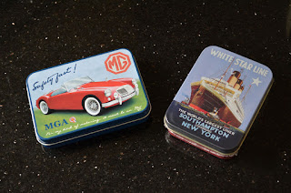
The first depicts the White Star Line and was bought for £3.50 at the Bressingham Steam Museum in Norfolk. They had other designs and it appears to be made by a company called Half Moon Bay in Bath. They are a wholesaler, but do have links to an online stockist – Kitsch-a-go-go – which has lots of different tins.

The second tin was found at the British Motor Heritage Museum at Gaydon and depicts an MGA sports car. It is also a little bigger than an Altoids tin and cost £4.

This was made by a company called Red Hot Lemon. It has a minimum order of £100 unfortunately, but you could always club together with someone else to buy some.

Now, all I need is another kit to build. What I'd really like is a 3W 40m and/or 20m radio transceiver, preferably synthesised so that you move around in frequency that would fit in a standard Altoids tin. So basically, a Steve Weber ATS or MTR – shame they are not being made in kit form. I have a three-band MTR v2 which is my pride and joy.

If you know of any other suitable kits please let me know by commenting below.

Thursday 28 July 2016

Repairing a cross-needle SWR meter

The SWR meter - working 100% again.
I've owned an AEA ET-1 antenna tuning unit for the last 20+ years. In that time I've had to replace the inductor switch as it burned out and also replace the meter.

Luckily, it uses exactly the same meter as MFJ ATUs so I was able to buy a replacement from them. I also resprayed the case at some point.

But recently the meter started playing up – it would only indicate 20W maximum forward power instead of 100W.

It was more of a problem on the less than 30W setting as I often use QRP radios and need to know if I am putting out 2W or 5W.

You could ask “why not just bin it?”, but that's not in my DNA!

Anyway, after asking for advice on the CDXC forum and looking at the schematic I decided that it could only really be down to a failed capacitor, resistor or diode. Given that semiconductors would be the first suspect I ordered two new 1N270 diodes from a UK supplier on Ebay for £3.98.

When they arrived I unsoldered the old ones, and checked them – one measured 1K Ohm resistance in both directions – not good and definitely not diode-like behaviour.

I soldered in the new diodes and bingo the meter is back to normal again. I've since ordered some 10 more 1N270s from China for just £1.12 inc. postage. These will do as spares.

I'm writing this as it might be useful to owners of cross-needle SWR meters in future. If you start to get low readings it may be the diodes. If you get no reading at all it is probably the meter.

Friday 22 July 2016

Elecraft K1 QRP radio finally finished

My Elecraft K1 (click to enlarge)

You could say that this project has been a long time in the making. The kit for this Elecraft two-band (40m/20m) K1 5W CW radio was actually a Christmas present back in 2004.

Heck, I still have the invoice for $329 plus the £44.97 import duty, making it about £230.97 at the exchange rate of the day (nearly £300 at today's rates).

When I first got the kit I had a couple of reads of the instruction manual, went “wooah” and put it in the loft. It even moved house with me eight years ago.

Anyway, a conversation with Colin M1BUU (a more enthusiastic QRP builder and SOTA operator you couldn't wish to meet) at the 2014 G-QRP Convention convinced me that I really should put it together.

In the intervening 10 years I have built a lot of other kits, including a Hunter SDR, Rockmites, MKARS 80 and a Steve Weber MTR, so I had picked up a lot of construction skills.

Last Christmas I actually started the build and, while not difficult, it was time consuming. Fast forward to July and I thought it was about time I finished it.

The build wasn't too bad, but I had a few problems, such as the wiring on the multi-turn pot for the VFO control – I thought the numbers on the side of the pot represented the numbers in the manual. They didn't.

I also managed to lose a couple of components down the back of the bench, which were subsequently found, and also couldn't find the insulating spacer for the power transistor – this I managed to improvise with insulating tape and fibre washers.

The final c*ck-up was missing out two capacitors, which meant the receiver didn't work at all. I'm glad I eventually managed to debug it without any help.

In all, I think I spent about 22-25 hours putting it together, but the end result is worth it.

The Elecraft K1 has a fantastic little receiver and a built in keyer and puts out around 7W if pushed. I have had a couple of QSOs with it so far and it is a very useable QRP radio.

I can thoroughly recommend it as a QRP project, although Elecraft have now moved on quite a way with the KX2 and KX3 - but then my K1 kit is 12 years old!

Tuesday 19 July 2016

Operating QRP from Beeston Bump (TG14) in North Norfolk

Update: YouTube video now available

Jim G3YLA and I operated HF and VHF QRP from the top of Beeston Bump in Norfolk as planned today.

It turned out to be the hottest day of the year, so not exactly ideal. Nevertheless, after parking up and walking to the top we were met by a fantastic 360 degree view.

I quickly set up by 40m inverted L end fed half wave (EFHW) on a 10m fishing pole, bungeed to a bench and fed it with my homebrew EFHW matching unit, while Jim tried some CW on 2m from a little beam. He didn't get anywhere with that so switched to FM and had a quick chat with some locals on 145.275MHz.

Once the HF antenna was erected I handed Jim the coax and he set to on 40m CW and quickly worked a station in Germany using 2.5W from his Yaesu FT-817.

Jim G3YLA working Germany on 40m CW.
I meanwhile tried to see what I could work on 2m FM and could raise the GB3FR repeater across the water in Spilsby, Lincolnshire, but there was no one on it. I switched to GB3NB in Norfolk and worked John G8VPE.

I then took over on HF, but 40m was hard work and 20m was not much better. I eventually went back to 40m CW using my 2.5W Steve Weber-designed Mountain Topper Radio (MTR) and raised fellow G-QRP club member Peter G3XJS near Wrotham, Kent who was using 5W to a doublet. I was very pleased to make the contact as that was the first time the MTR has been used in the field.

Looking at the Chilton Digisonde data I think this was via Sporadic E (Es) on 40m as the F2 critical frequency was only about 5MHz - we don't normally associate Es with 40m, but you could see the Es on the plot.

Jim G3YLA then took over again using his FT-817 and had a long CW QSO on 40m with a station in the Netherlands. 

The information board for the Y station.
There were a lot of walkers on the hill and we were able to explain what we were doing - it was quite apt as this was the location for the Beeston Hill Y Station, a secret listening post during World War Two. The chain of Y stations were on the front line, feeding Enigma intercepts to the War Office’s Bletchley Park.

There is an information board all about the Y station and the concrete foundations are still there.

Propagation was iffy at best and the heat was getting to us, so we decided to take the station down and head for the nearest pub for fish and chips and cold refreshments.

My home-made EFHW matcher and SWR
 indicator.
All in a great day and we both agreed we'll go back, perhaps in late September when propagation is better and the temperature is a bit more reasonable.

I also shot some video and I'll try and edit that over the next few days.
My three-band (40, 30 and 20m) Mountain Topper Radio.
3W CW on 40m raised Peter G3XJS in Kent.

Update:

I thought I would do a Reverse Beacon Network (RBN) check tonight.

I was pleasantly surprised to see I was picked up all over the place, including the US, from the top of the bump.

Jim G3YLA wasn't for some reason - not sure why as his CW is waaaay better than mine. Perhaps it was because he responded to CQs and didn't call CQ himself.

Reverse Beacon Network captures from the day -
chuffed I was picked up in the US (just) with 2.5W to an EFHW for 40m (click to enlarge).
Update: YouTube video now available

Saturday 16 July 2016

G0KYA to operate a "BOTA" station - "Bumps on the Air"

Beeston Hill near Sheringham in North Norfolk.
Image Wikimedia/Stavros1
I plan to operate QRP from Beeston Hill in North Norfolk on Tuesday 19th July as part of a new "BOTA" activation.

BOTA stands for "Bumps on the Air" a wholly-fictitious new organisation for radio amateurs who don't have access to real summits and mountains.

Beeston Hill (known locally as 'Beeston Bump') is not the highest point in Norfolk, but at 63m (207ft) above mean sea level it offers a good view of the coast and excellent HF take off.

I wanted to have some outdoor local QRP SOTA fun, but Norfolk is a little short of suitable summits (well, none actually) and Beeston Bump will have to do.

The highest point in Norfolk is nearby Beacon Hill at 103m (338ft), but I don't want to overstretch myself! Anyway, the view is better at Beeston and there are more ice cream shops nearby.

I've been meaning to do this for years!

Beeston Hill Y station circa 1940.
Image; Wikipedia.
I plan to operate 40m and 20m QRP CW using one or more of a variety of commercial and kit-built radios, including a Yaesu FT-817, Elecraft K1, Mountain Topper Radio (MTR) by Steve Weber KD1JV and a 1W Rockmite. Antennas will be end-fed half wave (EFHW) dipoles.

Beeston Bump is no stranger to Morse code. Beeston Hill Y Station was a secret listening post located on the summit during World War Two. The chain of Y stations were on the front line, feeding Enigma intercepts to the War Office’s Bletchley Park.

There are no awards for working me on Beeston Bump, no certificates and no special QSL cards - just my normal one. And just the fun of working CW at about 16-20 wpm around the usual QRP watering holes on 20 and 40m. I hope to be there from about 10:30am.

Jim G3YLA, a fellow QRP enthusiast, might be with me too.

(With apologies to the excellent Summits on the Air (SOTA) organisation!)

Friday 27 May 2016

Updated UK HF prediction charts

I've now updated my hourly UK HF Propagation Predictions maps for the rest of 2016.

You can view the charts using the link on the right or at infotechcomms.co.uk/propcharts/

These take into account the latest smoothed sunspot numbers from NOAA/NGDC.

We continue to see a steady decline in sunspot activity as we fall away from the peak of solar cycle 24. Twelve months ago the solar flux index peaked at 163 in May. This month it has struggled to exceed 100 and is currently 94.

Coupled with this, we have suffered quite badly from the effects of plasma from solar coronal holes. These are areas of the sun with an open magnetic field that allows plasma to escape.

If these coronal holes are earth-facing the result can be an elevated K index as the plasma from the high-speed solar wind stream impacts the earth, especially if it has a negative or south-facing magnetic field, which couples more easily.

A high K index is usually a sign of poor HF conditions, with noisy bands and depressed maximum usable frequencies. Any path over the poles is also badly affected.

This can also lead to aurora, which while not being visible in the summer, can lead to openings on VHF.

The RSGB Propagation Studies Committee is also pleased to be able to present its latest HF propagation prediction tool, which is currently hosted at www.predtest.uk

This is still being developed and uses the newer ITURHFPROP software as its backend, rather than VOACAP.

We encourage amateurs to use the system, which can also be used for point-to-point predictions using a prototype tool called 'Proppy'.

Gwyn G4FKH, who is project manager for the new system, welcomes feedback. The goal is for the whole system to be moved to the RSGB website once finished.

Thursday 19 May 2016

Sporadic E season is under way

The Sporadic E (Es) season on 10m and 6m is well under way with lots of useful openings.

I was having a listen around 28MHz today and was struck by how many 10m beacons are audible when there doesn't appear to be any other activity on the band.

And they aren't high powered either. First I heard OK0EG on 28.2825MHz in the Czech Republic and a little late OY6BEC in the Faroes on 28.235MHz. Then a little later still I spotted a spike on the IC-756 Pro3's panadapter and it was F5ZWE near Toulouse on 28.2427MHz.

You can get a current list of 10m beacons, complied by Martin G3USF, at: http://www.keele.ac.uk/depts/por/28.htm

These are all running 10-15W and simple antennas, yet can reach S6-9 in the UK when the conditions are right.

We still don't completely understand Sporadic E, although the current thinking is that it is due to wind shear in the upper atmosphere that pushes ions together into clumps or clouds. The ions may come from meteors. Jim G3YLA, who is a professional meteorologist, is also looking at whether these winds, when they pass over mountain ranges, are forced upwards and create these "gravity waves" that force the ions together.

I also have a theory that solar flares can contribute to SOME of the ionisation on occasions, but mainly outside of the May-August period - there are plenty of instances of Es without any flare activity. I have some plots of Es in late April that correlate very well with solar flares.

Anyway, Jim posts some daily high-level wind charts in an attempt to understand what is happening. 


Steve G0KYA

Friday 4 March 2016

Working the International Space Station with 2m APRS

The proof - G0KYA works RS0ISS as shown
at www.ariss.net, along with other EU stations.
Yippee! It works! Yesterday I wrote about how I had managed to get 2m APRS working on my Icom IC-7400 using Soundmodem, UISS and a program by G8BPQ to connect a virtual comm port to the Icom CI-V interface to key the radio.

It all seemed to work on terrestrial APRS on 144.800MHz, but the acid test was whether it would connect with the APRS system on the International Space Station (ISS) on 145.825MHz.

I already knew that it could decode packets from the ISS, but would the ISS be able to decode me?

So this morning it was time for a test. Using a 2m Slim Jim in the loft, I wound the Icom IC-7400 up to half power and waited for the ISS pass between 10:11-10:20hrs. This was a maximum 73 degree pass here in East Anglia.

Actually – small confession. I thought the IC-7400 was a maximum 50W out on 2m, when it is actually 100W (when I looked at the manual). So I was actually using 50W not 25W.

The 50W power might be a little excessive, but my coax is only RG58 (although it is only about 12m) and the antenna is a compromise in the attic too, so the ERP was probably more like about 20-25W. I figured that if I could connect with 50W I could reduce it on other passes and see what QRP power would do.

This attempt was just to prove that the system (with a software modem and not a packet TNC) could work.

Anyway, using the UISS program I put in my locator square (JO02NN) and details and waited for the pass.

The ISS became audible at about 10:13hrs and I adjusted the rig's frequency to about 145.828MHz to allow for Doppler.

The system decoded quite a few packets and I keyed the UISS APRS TX button.

The Doppler shift fell away as the ISS got closer and at 10:16:09hrs I was successful – RS0ISS heard G0KYA. Yippee! So now I can apply for the ultimate QSL card.

You can check whether you have been heard at http://www.ariss.net/ and this will also plot your location on a map. You can get the details of how you apply for a QSL card at: http://www.ariss-eu.org/traffic/european-qsl-bureau

Some learning points though:

1. Spend some time getting your latitude and longitude absolutely spot on. Just using the locator square of JO02NN put me about half a mile away from actual location. The easiest way to do this is with APRIS32 and zooming in on the map to get the exact degrees, minutes and seconds of your lat. and long.

2. Keep an eye on the Doppler shift. This can vary from about +3.5kHz to -3.5kHz over the whole pass. Orbitron will calculate this for you. It does mean that at AOS your TX frequency will have to be lower than 145.825MHz and you you will listen higher. At the time of closest approach they should be both be about 145.825Mhz, and that might be the best time to attempt the contact.

3. Use a small beam rather than an omni-directional antenna. I have a tiny three-element delta loop beam that I may fix pointing due south at about 35 degrees elevation to see how that fares. It might be better for the ISS, PSAT and the other satellites.

4. Use better coax. RG58 isn't ideal for VHF – the only reason I used it was because I normally use that run for HF. I had three lengths put in between the shack and the loft when I first moved in. As it is only about 10-12m long the losses are about 2dB on 2m. Low enough for the limited VHF work I do, which normally amounts to local 2m FM work only.

But as an experiment the ISS APRS contact via Soundmodem worked, showing you don't need to have a hardware packet TNC to work the ISS on APRS - or complex antennas.

Update 5th March 2016

I reconfigured the station for my daughters, who are both licensed. At 07:48hrs Ellie M6ELE got through with 10W. Her digipeated signal was captured from the ISS by PD0SBH-10 in the Netherlands.

On the next pass Sarah M6PUP also got through with 10W and the return signal was picked up by ON7EQ-10, so my thanks to both stations.

Jean-Jacques ON7EQ has a stonking ground station - see www.qsl.net/on7eq/en/index.htm

Thursday 3 March 2016

2m ISS APRS on the Icom IC-7400 with Soundmodem

The UISS software for sending packets to/via the ISS.
After my recent work on the Tim Peake ISS contact project I was quite taken with the idea of being able to contact the ISS using 2m APRS data on 145.825MHz.

I haven’t really played with packet radio for years and sold my TNC in the dim and distant past. But I read that you can use a software-based modem now instead of a TNC.

I already had a data interface that would work with my Icom for RTTY and PSK31.

So it couldn’t be that hard to get APRS running, could it? I never learn!

Firstly, we have got two APRS experts in my local club (Norfolk Amateur Radio Club – James M0UKS and Kevin M0UJD who could write a book on the subject), but even a chat with them left me none the wiser. But I eventually figured it out, so thought I would share the details.

The problem is that Soundmodem (the software modem that you can use for APRS) expects to see a signal on a serial port to transmit or key the PTT. Icom, on the other hand, uses its CI-V interface to send a command.

I messed around with this for days, but eventually came up with a solution, thanks to John G8BPQ. He has written a small program that creates a virtual serial port. He then has another program called CAT7200 that translates the rig’s CAT control command and sends it to the virtual serial port. The result is that the rig then transmits.

So what do you need to set up APRS on an Icom IC-7400 or IC-746 Pro? I would imagine that this would work with the IC-706, IC-7000 and IC-7410 too.

Firstly, I’ll presume you have a data interface for RTTY/PSK connected up and working with your PC. Secondly, I’ll presume you have a CI-V interface connected between the radio and the computer too – the type that sends the frequency and other information to your logging program, for example.

Now you need to do the following:

1. Download and install Soundmodem from http://uz7.ho.ua/packetradio.htm

2. Download and install UISS from http://users.belgacom.net/hamradio/uiss.htm

You should be able to configure the two programs and receive packet data on 144.800MHz (if in the UK) or from the ISS or PSAT on 145.825MHz.

Quick tip – make sure Soundmodem is set to look for tones on 1200/2200Hz – I must have changed mine by mistake and although I could see the packet tones on the waterfall it wouldn’t decode.

Orbitron let's you work out when the ISS is overhead,
as well as other packet-enabled satellites like PSAT.
I won’t go into any more detail on UISS or Soundmodem as there are better reference documents out there, but if you’ve got this far you are half way there.

Now to enable TX.

Go to http://www.cantab.net/users/john.wiseman/Documents/CAT7200.html and download the file CAT7200.zip. Unzip it into a suitable folder.

Now go to back to the CAT7200 web page and follow John's instructions for creating a virtual serial port using the files you have just downloaded – there are instructions for XP and Windows 7.

Once you have created the virtual serial port it should appear in your Control Panel. You now set up Soundmodem to trigger this Com port in devices >> PTT Port.

Now the clever bit. Run CAT7200 and set it up to watch the virtual serial port you have created (on the left of the screen) and to trigger the CI-V CAT port you use (on the right of the screen).

Now, if you send a packet from UISS it should put the radio in TX first. Just make sure you get your audio levels right.

As for how you send a data packet to the ISS please see http://amsat-uk.org/beginners/how-to-work-the-iss-on-aprs-packet-radio/


Friday 26 February 2016

Today's Tim Peake ISS contact was a great success

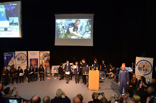
I was so proud to be part of the team that let youngsters talk to astronaut Tim Peake on the ISS from the CNS School in Norwich today.

There wasn't a dry eye in the hall!

The lowish six-minute pass went incredibly well thanks to the technical team from ARISS.

Each of the youngsters got to ask a question and we even got in a few more. Good video link too.

Norfolk Amateur Radio Club has been heavily involved in the event and helped run workshops at the recent "Ground Control" day.

Our special event station with the call MX0YHC also made around 100 contacts on 40m thanks to Chris G0DWV and Andy M0NKR.


Good luck with the next link-up

Sunday 21 February 2016

Worked All States, QRP and magnetic loops

MFJ-1786 magnetic loop for 30m-10m
This weekend was the ARRL CW DX contest where US stations work the rest of the world. This was a good opportunity to try and work the rest of the states I need for my Worked All States award.

I need Alaska, North Dakota, South Dakota, Wyoming, Rhode Island, West Virginia and Nebraska.

I have actually worked quite a few of these, but those stations are not on Logbook of the World (LOTW).

Anyway, starting at the bottom of 14MHz I soon came across KI1G in Rhode Island and bingo! He was in the log with 100W to the OCFD.

I never found any of the other states I needed, but on Sunday I came across N8II in West Virginia and bingo, worked him too. Unfortunately, he isn't on LOTW – damn! I'm not sure if you can do a mixed entry with part LOTW and part QSL cards, like I did with my DXCC application. It might come to that.

Anyway, with no sign of the Dakotas or Nebraska (don't even mention Alaska), I thought it would be fun to try some QRP.

With just 5W I soon worked Connecticut, Pennsylvania and Massachusetts with the OCFD. Time to up the game.

So I rigged up my MFJ-1786 mag loop on a 12ft pole in the back garden. This was about two S points down on my usual 40m half-wave OCFD, but I was able to work the eastern states on 20m in very short order. I also worked N2IC in New Mexico, W2UP Colorado and N9RV Montana on it.

So what about QRP and a magnetic loop?

A bit harder, but North Carolina, Tennessee, Vermont and Virginia were soon in the log with 5W on 15m.

Now, don't get me wrong, it is the antenna at the other end of the contact that was doing all the hard work, but if anyone says they haven't got room for HF antennas tell them about the MFJ-1786. It's a miracle for hams with little space.

So I'm hoping that Rhode Island gets confirmed on LOTW. I then need to think long and hard about Alaska. That is going to be a tough one. And if I can get the others confirmed with QSL cards Worked All States (WAS) is a possibility.


Friday 12 February 2016

Radio Norfolk interview about Tim Peake and ISS

ESA astronaut Tim Peake.
I was lucky enough to hear astronaut Tim Peake's ISS contact with another UK school on Thursday 11th February 2016.

Not only did I record it, but I sent out a press release and ended up being interviewed about it by BBC Radio Norfolk.

The Norfolk Amateur Radio Club had put on a workshop the next day at the City of Norwich School for students who are going to be involved in their contact with Tim in two weeks, so it was very fortuitous.

You can hear the ISS downlink on 145.800MHz and you don't need a particularly fancy antenna.

If you do hear and record Tim do contact your local media as they are fascinated by the whole business and it brings good PR for amateur radio in general.

Anyway, here is the audio from Radio Norfolk in MP3 format.


Saturday 9 January 2016

HF Propagation charts for the UK updated

I've now updated my propagation prediction charts for the UK through to April 2016.

See http://www.infotechcomms.co.uk/propcharts/

I've used the latest smoothed sunspot numbers from NOAA in the US. There is little point in updating them much further than four months as the SSNs change, and it takes me about three hours to do four month's worth of charts and upload them - that's a chart for every hour and for every band or 24 x 8=192 charts per month.

It is interesting to see how the solar cycle is falling away. In January 2015 the SSN was 62, now it is just 45. The coming months will see further falls.

This means that we will see fewer openings on 12m and 10m, but 15m should still open up at times. I worked the US Virgin islands on 15m CW this morning and it was open to the eastern seaboard of the US this afternoon so don't write it off.

The new
web based version of ITURHFPROP
The RSGB Propagation Studies Committee, of which I am the chair, is also working on a new online HF prediction system based on the ITU program ITURHFPROP.

This uses a different, but newer, ionospheric model to the VOACAP engine normally used, but the original ITURHFPROP software is not very easy to use.

But thanks to the work of Gwyn Williams (G4FKH), James Watson (HZ1JW) and Chris Behm we are getting closer to a web-based version. You can try the test model at http://www.predtest.uk/

Ultimately, it will have the ability to produce point to point predictions as well, just like VOACAP Online. But lets learn to walk before we run.

It will be interesting to compare the two models and Gwyn would welcome any feedback. His email details are on the web page for the new model

Friday 8 January 2016

Tim Peake - first UK schools contact on 2m from ISS

ESA astronaut Tim Peake. Image: Steve Nichols
Tim Peake, the UK ESA astronaut, made his first schools contact this morning, 8th January 2016.

The ISS appeared over the horizon here in eastern UK at 08:49hrs and vanished at 08:55hrs. I monitored the downlink signal on 145.800MHz and it appeared at about 08:52hrs. Tim appeared to be having problems with the original uplink frequency and so they switched to another.

It was a short pass, but the school - Sandringham School in Hertfordshire - still managed to ask some questions. Unfortunately, they lost the ISS signal before they finished and were able to say goodbye.

I've attached an audio recording of the pass as captured via a 2m Slim Jim in the loft and an Icom IC-7400. The recording was made with RecAll and processed with Audacity.

I also heard him at times on a 2m handheld, but I wouldn't recommend it as it was not as strong.

I'm very proud to be be part of the team that will enable the next schools contact in late February 2016 when Tim will talk to the CNS School in Norwich. The exact date and time has yet to be decided.

I was lucky enough to interview and photograph Tim professionally for "ADS Advance" magazine last year.

Download the MP3 audio file of Tim Peake