Thursday, 24 December 2015

SAQ transmission on 17.2kHz from Sweden, 24th December 2015

The 200kW Alexanderson alternator
I heard and recorded this morning's 200kW SAQ Christmas transmission from the Alexanderson alternator at Grimeton, Sweden - see http://alexander.n.se/

I used a Perseus SDR and a home-made miniwhip to Roelof PA0RDT's design at about 8m high. The signal was loud at about S9 +20dB - much better than I thought it would be, but this was down to the brilliant tiny antenna.

I managed to extract the audio and make an MP3 file from it, so you can hear it yourselves and decode the CW if you wish. Note that at the end of the MP3 file you'll hear the tone die away as they switch the alternator off and it slows down!

There are few glitches as the computer struggled to record it, but you only lose the odd character!

Download the MP3 file

Monday, 21 December 2015

Rockmite 40m fixed and working

I unearthed my 40m Rockmite that I built years ago for a QRP session today.

First problem I noticed was that it wouldn't work with a paddle, only a straight key. The second was that I only had audio from one of the ear buds.

I thought this was a dirty connection so tried cleaning the contacts – no good. Turned out to be a poor joint on the back of the 3.5mm socket. In fact, I'm amazed it ever worked at all!

Now on to the problem with the paddle. The Rockmite will default to straight key mode if you fire it up with a straight key attached and that should have been the clue.

Pulling the front panel off I could see that the quarter inch socket for the Morse key/paddle had rotated and was shorting out one of the contacts that would normally go to the middle of the plug.

The Reverse Beacon Network proves you are getting out!
Once that was sorted the keyer burst into life. Connecting the Rockmite up to a W5GI dipole and sending a few CQs showed that I was being picked up all over Europe with about 0.75W (I normally send “1W” as it is easier).

Anyway I answered a CQ call from DF1UQ QRP he came back to me – wonder of wonders. I gave him 559 and he gave me 529. Turned out Klaus was running 4W. There was a lot of QRM from other stations in the late afternoon so I kept it fairly short, but the Rockmite works again.

I still think the sidetone is a bit harsh, but there is a mod for that if I was that bothered. You'll also see that I have a knob on the front that says VXO. This was an attempt to connect a variable capacitor in line with the crystal to allow me to move the frequency a little. All I got was hum so I abandoned that – one day I'll have another go.

I still think the 40m Rockmite has an amazing receiver for its size and price. The newer ones from Kanga UK/QRPMe are even better. It is definitely better than the Foxx-3, although that is self-contained. Both nice QRP projects to build though.

I'm trying to clear the decks of QRP projects/repairs so that I can concentrate on building my Elecraft K1 kit that was a Christmas present in 2004 – about time it was built I think!

Update 31/12/15
Just replaced C8 with a 0.01uF capacitor and that has quietened down the sidetone volume a little. Also put a 6.8mH choke in line with the crystal and small polyvaricon and am getting about 2.5kHz of swing around 7.030MHz which makes it a little more versatile. This was at the end of the crystal nearest Q2.

Wednesday, 16 December 2015

20m Spitfire Rockmite is joined by 40m FOXX-3


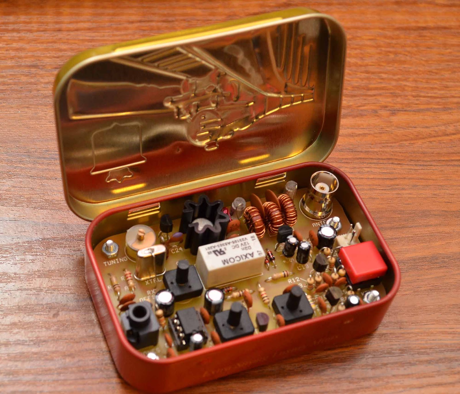
The 40m Foxx-3 - the big red button is the Morse key.
Click to enlarge any image on this page.
Back in July I wrote about the 20m Rockmite I built into a Stewart's mint tin. Well, now it has been joined by a 1W 40m FOXX-3 transceiver, also from Kanga Kits in the UK, but this time we have a steam locomotive on the lid.

The Foxx-3 is a well-known design that has evolved from George GM3OXX's original Foxx into its latest “-3” incarnation, designed by Derek G4GVM.

I won't go into how it works – you can find out more on the Kanga web site.

The build was quite easy – the first thing to do it drill the mint tin for the PCB stand-offs and open up the holes with a needle file. I used the PCB as a template for that.

The build sequence has good documentation, all the stages are in different bags and you can test each stage as you go.

The first stage to build is the audio amplifier with an LM386 and you test that by touching the volume control connection and seeing if it hums – no problem.

The second stage is the keying circuit, which again is easy to check. I opted for the push button Morse key on the board rather than a socket for a Morse key as this is really just a toy for me.

A slight amount of switchover delay is set by the value of a resistor. I stayed with the suggested value and that seemed fine.

The third stage is the sidetone circuit, which once again worked first time.

Stage four is the crystal oscillator and I had an issue here that when I keyed up the TX note was very wobbly. I read elsewhere that this can be normal until you build the final stage to give it a decent load. This turned out to be the case.

Testing testing!
The final stage is the power amplifier and filter, complete with four tiny toroids. Again, not difficult, but make sure you get the coating off the enamel before you finally solder the toroids in. I used a drop of molten solder on the iron to do this and it seemed to work OK.

The final stage was to put the BNC on the board and I had to increase the temperature of the iron for this as it acts as an effective heat sink.

Finally, it was a case of wiring it up to a 12V lithium ion battery, connecting a a 40 OCFD antenna and headphones and seeing if it worked.

The power output was just under 1W so I left it as it was – you can change a resistor to increase/decrease the power level up to 1W maximum.

Well, the RBN picked it up even if no one came back to me.
Using my Icom IC-756 Pro3 I checked where it was transmitting and adjusted the variable capacitor to put it on 7.030MHz. I then transmitted on 7.030MHz on the Pro-3 to adjust the sidetone offset. I found that this had a limited range before the receiver either went deaf at one end of the range or just hummed at the other. I did quite a bit of to-ing and fro-ing until I was happy – you'll see that one of the skimmers logged me on 7.0299MHz as I adjusted it.

I think that once it is set it is best to leave it.

I also found that I needed to use my ATU to avoid AM breakthrough on my W5GI dipole – the 40m Windom was OK. I had been warned about this.

The finished item in a Stewart's mint tin.
A few CQs using the built-in Morse key had me spotted on a few RBN skimmers in Europe. You can see that my reported speed varies from 13-15wpm as it is very hard to be consistent with a push button Morse key! It is also hard to send the highly-accurate Morse needed for skimmers to decode you, so I was pleased to be picked up in the UK, Ireland, Belgium and Germany during the daytime.

The reported 15-20dB SNR means it should be possible to work people with 1W, although no-one has come back to me yet and I haven't heard anyone call CQ who has been spot on my frequency.

The receiver is reasonably lively and you'll hear anyone who can hear you I guess.

The only issues were mechanical – make sure that when you put it in the mint box that you have enough room for the BNC plug to fit. I need to open up the holes on the PCB board by about 0.5mm to allow space for it to be connected. Doh!

I also had to grind down the three controls on the variable resistors to allow the lid to shut properly.

In all then, the Foxx-3 is a great little kit to make and it obviously works. Don't expect Elecraft KX-3 performance though! It only costs £29.95.

I do think that you will work other hams on it though, at least on the 40m version, and my thanks to Dennis at Kanga for selling it. The next project is an Elecraft K1 kit that I bought back in Christmas 2004 and has been living in the loft unassembled ever since. Shame on me!

Incidentally, the tiny zip-up nylon camera cases for sale in Poundland are ideal for storing and carrying mint box radios like the Rockmite and Foxx-3.


Thursday, 15 October 2015

Getting more bands out of a 40m OCFD (Windom)

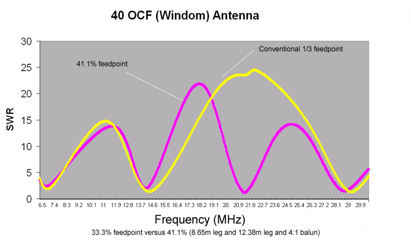
The original design in my book for a flat-top
optimised 40m OCFD (click for larger image).
In my book “Introduction to Antenna Modelling” I talk about how you can get more bands out of a 40m off centre fed dipole (OCFD – sometimes incorrectly called a Windom) by adjusting the feed point position.

The conventional feed point is at the 33%/66% point, but if you do that with a 40m OCFD (roughly 20m long) you find that you get 40m, 20m and 10m, but 15m offers a high SWR.

But the model shows that by adjusting the feed point to 41% you can get a low SWR on 15m too.

But this is just theory – does it work in practice?

I thought I would try it in real life and see how it performs. The only trouble is I wanted to erect the antenna as an inverted V, so would that affect the lengths and feed point in the MMANA-GAL model?

Anyway, after an afternoon of fiddling with MMANA-GAL I ended up with an answer – an antenna with a total length of 20.75m (8.5m and 12.25m for a 41%/59% feed point), fed with a homemade twin core 4:1 balun and mounted at about 8.5 metres, fed with about 25m metres of Mini8 coax.

The model I ended up with suggested low-ish SWRs on 40 (actually, just over 3.1:1), 20, 15 and 10m, with not so good matches on 30m and 17m, as expected.

Now to turn it into a real antenna. If you use PVC-coated wire, you'll end up with an antenna that has to be shorter than calculated due to its velocity factor being less than one. That is, the speed of light is slower in a denser medium.

Every antenna I have ever designed with MMANA-GAL has ended up shorter than calculated.

So applying an estimated velocity factor of 95% I ended up with two legs of 8.075m and 11.637m. I cut the wires a little longer than this and twisted the ends over to allow for a little adjustment – I fully expected to have to shorten the wires once it was up.

Having hauled it all into position at the top of a fibreglass fishing pole I checked the SWR at the end of the coax and was pleasantly surprised. It was pretty much spot on, with an SWR less than 3:1 on 40, 20, 15m and 10, and my internal ATU could also tune 30m and 17m, although obviously its performance is down a little on those bands.

Lengthening it a little might put the lowest SWR points a little more mid-band, but we are only talking about fractions of one SWR point.

The model shows it is a cloud warmer on 40m (good for NVIS contacts), and the multi-lobe pattern on the higher bands is complex and not always ideal for DX, but this is a compromise antenna.

Early tests have been promising, with the antenna performance matching dedicated dipoles on the bands on which it is resonant. So I think it is a success.

Actual SWR figures (at end of 25m of coax)

7.100MHz 1.9:1
10.120MHz 3.3:1
14.175MHz 2.5:1
18.100MHz 3.0:1
21.225MHz 1.2:1
24.940MHz 2.2:1
28.500MHz 1.4:1

Update: Well, I've been using it for a day and have worked Cuba (CO), Moldova (ER), Qatar (A71), Saudi Arabia (HZ) and Ceuta & Melilla (EA9) on 15m where it seems to go great guns. 40m has given strong contacts into Europe. I like it.

Update, February 2016
I've now been using the antenna for about four months so here is an update. It works very well on 40m, and is consistently equal to or down about 0.5 S point on my W5GI. I haven't used it much on 10MHz, but it looks to be slightly better than the W5GI. It works very well on 14MHz and 18MHz and is really good on 21MHz. Again, I haven't used it much on 12m, but it plays on 10m, although it is consistently slightly worse than a dedicated half-wave dipole by about 1-2 S points. Overall, not bad for a multi-band antenna.

A typical 4:1 two-core Guanella balun.
As you can see below, someone asked about the balun. It is a Guanella design wound on two FT140-43 cores. Each core has about 13 turns (from memory) of twin loudspeaker wire.

The cores are then put back to back and wired with one side in series and the other in parallel. If the characteristic impedance of the twin wire is about 100 Ohms this gives the required 200 Ohms/50 Ohms = 4:1 impedance transformation.

The current thinking is Ferrite Type 61 for the top end of the HF range; Type 43 for the bottom end; or Type 31 for the best compromise across the range. The image is not of my balun but it is of a similar design. Mine is housed in a box with all the joints sealed with tape for waterproofing purposes.

Monday, 12 October 2015

RSGB Convention, October 2015

I gave two talks at this year's RSGB convention. The first was on HF Propagation and I'd like to remind readers that I have a video presentation with audio that is available for RSGB-affiliated clubs.

If you would like your club to have a copy get your programme secretary to drop me an email at steve [at] infotechcomms.co.uk. I can also do a Skype-based Q&A after the presentation in most cases.

Otherwise, there is always the free "Understanding LF and HF Propagation" e-book to download.

The other presentation was on "An introduction to antenna modelling with MMANA-GAL". This is available for download. Don't forget that my three books are also available from RSGB ;-) or you can use the links on the right.

Sunday, 27 September 2015

Amateur radio from a submarine - W7SUB

USS Blueback, W7SUB, Portland, Oregon
I'm lucky enough to do some business travelling every autumn (fall) and am currently in Portland, Oregon, USA.

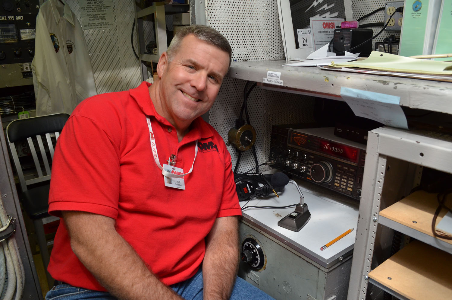
I was even more lucky to do some operating from the submarine USS Blueback at the Oregon Museum of Science and Industry (OMSI) this morning, thanks to Joe KF7UOQ.

We operated SSB and CW on 17m, 20m and 40m and I managed to work a few stations, including as far afield as Wisconsin (17m CW) and a SOTA station Todd W7TAO using 5-10W CW on 40m - conditions were not brilliant.

We organised a sked with Dean KG7MZ in Washington State via 2m (after a fire alarm went off!) and worked him on 40m CW too. I thought the fire alarm was part of the sub's sound effects and stayed put - duh!

I used QRP to stop interference to Joe on 20m. Joe worked Texas and a host of others on 14MHz SSB.

My CW was a little jerky at first until I got used to the sub's straight key - W5NNS must have wondered what he was working!

Antennas are a vertical for 20m and a dipole for 6-50MHz (from memory). W7SUB is obviously at river level and surrounded by buildings so not the best location for HF.

Joe KF7UOQ
USS Blueback (SS-581) is a Barbel-class submarine formerly in the United States Navy. I was amazed to see it actually has three decks and was nowhere near as claustrophobic as I thought it would be. Having said that, not sure I'd want to be underwater on active service on it!

USS Blueback appeared in the 1990 movie "The Hunt for Red October".

On previous trips to the "left coast" I've been lucky enough to operate on the Queen Mary, USS Midway and at K6KPH at Point Reyes/Bolinas north of California.

The USS Blueback Radio Room
Very nice to be able to include amateur radio on a business trip. Thanks again to the team at W7SUB (what a callsign!) including Joseph Noecker K7FGN who helped organise it.

You can click on the images to see a bigger version.

Steve G0KYA/AB8ZV

Friday, 11 September 2015

SSTV images found from Space Shuttle Challenger, 1985


I had a really big surprise this week. My local club - Norfolk Amateur Radio Club - were having a retro technology evening. This involves people bringing in equipment like Sinclair Spectrums, BBC Bs, old calculators etc - even an Oric Atmos showed up this year.

The highlight for me was a 1982 Betamax video recoder and Sony UHF telly, complete with videos of the news and BBC's "Multi-Coloured Swap Shop" with Noel Edmonds, thanks to Robert G4TUK.

Anyway, I took my Sony Walkman Professional, a couple of old Macintosh computers and a 1978 Russian Vega Selena shortwave radio - still working. While I was looking for the Walkman I found an old box of cassettes with one marked "Space Shuttle August 1985".

This turned out to have 2m SSTV signals on it from Tony England W0ORE's STS-51-F mission.

The recording was a bit noisy as I think I used a Slim Jim, and in those days I used a Sinclair Spectrum to decode the images. But what could I do with it in 2015 - 30 years later.

I researched this and he used a Robot 1200C to encode the SSTV images. I was able to use RX-SSTV to decode some of the black and white 8-second images and the Robot 36 ones. They won't win any awards but you can definitely see what they are - one is Tony himself and the others are of the Shuttle's cargo bay, with the telescope it was carrying, and the earth.

The most chilling thing is the Morse ident in between the images which reads "W0ORE/CHALLENGER".

Less than a year later, in January 1986, Challenger was no more after exploding shortly after launch.