Showing posts with label antennas. Show all posts

Thursday, 1 November 2018

Autumnal HF conditions show sunspots aren't everything

Click to enlarge

Don't you just love it when something works! I took down my multi-band end fed half wave (EFHW) antenna last weekend and replaced it with a home-made 40m off-centre fed dipole (OCFD).

The EFHW worked, but I was never happy with the performance. This may be due to the inverted L configuration or the compromise 49:1 ferrite-based Un-Un. Either way, I felt I was missing out on some DX and was keen to try something else for the Autumn/Winter.

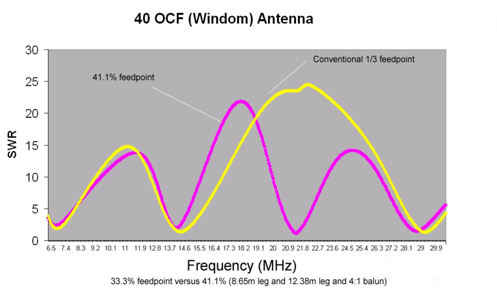
The 40m Windom is about 66ft long and has a home-made 4:1 Guanella balun made with two ferrite cores. It is fed at the 41%/59% point so it covers 40, 20, 15 and 10m with an SWR below 3:1 and the other HF bands with an ATU.

The apex is at about 8m with the ends down to about two metres, so not ideal.

Nevertheless, in back-to-back WSPR tests it proved to be better than my W5GI dipole that goes over the roof by about 7dB on average. This was good as the EFHW was mostly down on the W5GI.

Anyway, I thought I would leave it running on 20m WSPR for 24 hours to see what it could pick up. This was with zero sunspots, but a Kp index of 1. I was delighted to see that I had been picked up as far afield as Japan, Australia, Alaska, Antarctica and Brazil. The furthest west I got in the US was Utah.

So, I'm a happier bunny. I might return to the multiband EFHW one day, perhaps looking at different ferrite mix configurations for the Un-Un, but for now I'll stick with monoband EFHWs with tuned iron toroid/capacitor matching units that work well.

The OCFD can stay up for a while - you know that the best antenna you can have is either the one you just took down, or the one you are going to put up, not the one you are using!

Monday, 24 April 2017

A portable multi-band End-Fed Half Wave (EFHW) antenna for 40-10m

The camping washing line spool used for the antenna wire.
A few people have asked about the 30m antenna Norfolk Amateur Radio Club used for its International Marconi Day (IMD) operations at Caister Lifeboat this year.

Ten Megahertz (30m) turned out to be a useful band for us, allowing CW contact after CW contact, despite poor conditions after a geomagnetic storm and a K index of five.

The antenna we used was a portable 40-10m multi-band end-fed half wave (EFHW) with a 49:1 Unun using an FT240-43 toroid.

It used a wire 9m vertically metres up a fishing pole and then about 5.8m out.

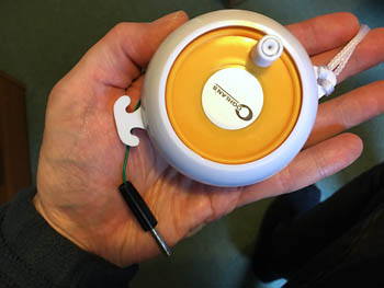
The novel thing was that I only built it the day before and it uses a Coghlan camping washing line spool with the string taken off and about 21m of wire wound onto it.

Caister Marconi radio station makes nearly 200 contacts


Right: Rodney G0CBO and Kim G4WUG contact another other 
radio amateur with Morse code from GB0CMS at 
Caister Lifeboat on International Marconi Day.


Members of the Norfolk Amateur Radio Club (NARC) managed to contact 193 other radio amateurs in 31 different countries on Saturday 22nd April 2017 when they took part in the annual International Marconi Day at the Caister Lifeboat Visitor Centre to mark the inventor's birthday.

Using the call GB0CMS and a mixture of Morse code, telephony (speech) and data (PSK), contacts were made with other radio amateurs across the UK, Europe, Australia and the USA.

Notable contacts were with other special Marconi stations in the UK, Italy, and Ireland.

NARC ran the all-day special event station at Caister Lifeboat to commemorate the village's original Marconi Wireless Station, which was established at Caister in 1900. The station was in a house in the High Street known as Pretoria Villa and its original purpose was to communicate with ships in the North Sea and the Cross Sands lightship.

On Saturday, the closest to Guglielmo Marconi's birthday, stations around the world are set up at sites with historical links to the inventor's work. These include Poldhu in England; Cape Cod Massachusetts; Glace Bay, Nova Scotia; Villa Griffone, Bologna, Italy and many others.

Visitors to the station including many other local radio amateurs and members of the public.

Steve G0KYA, who organised the event, said: “Conditions weren’t brilliant due to the effects of a solar coronal hole, but we started off by talking to Ian VK3MO, an amateur near Melbourne, Australia on SSB.

“We then went on to make contacts with other radio enthusiasts all over Europe and as far as North Carolina, USA using speech, PSK and Morse code.

“New this year was CW operation on 30m, which proved very effective with long runs into Europe using a new prototype end fed half wave antenna (EFHW). We also had the club IC-7300 running on 40m, which worked well but highlighted a few things we need to check, such as the overload light flashing when the other station was on 30m and we tried to work on 20m.”

“My thanks to everyone who helped on the day and to to Caister Lifeboat for letting us set up the station.”

The equipment used was 100W from an Icom IC-756 Pro3 (30/20m) and Icom IC-7300 (40m). Antennas were a W5GI dipole on 40m and G0KYA's monoband end-fed half-wave verticals for HF.

Wednesday, 30 November 2016

Quarter wave verticals for HF

The radiation pattern for a quarter wave vertical.
I had an email from a radio amateur who was struggling to work DX after putting up a very off centre fed dipole cut for 40m and fed with open wire feeder.

This is probably not the best way to go about it as the off centre feed can cause an imbalance and create RFI problems.

I suggested a better DX antenna might be a quarter wave vertical cut for the band in question and fed against a decent ground plane. But what is a decent ground plane?

Rudy Severns N6LF has done extensive research on this, but his conclusion was that you really need as many radials on the ground as possible. Up to 120 is optimal, but you will notice an improvement as you add more and more with perhaps 16-32 being the minimum for good performance.

Don't be misled by your SWR meter as a single earth stake may give you a low SWR, but what you are seeing may be the effect of ground losses.

A quarter wave vertical should have a theoretical impedance of about 35-36 Ohms, so if you have a 1:1 match you are seeing 35 Ohms, plus 15 Ohms of ground losses.

As you add more and more radials the SWR may INCREASE. This shows it is starting to get closer to the optimum 35 Ohms.

The goal is to keep on adding ground radials until the SWR stops changing. Then the vertical is working about as good as it can.

Rudy found that once you get above 32 ground radials the improvements start to get more subtle and increasingly minimal.

But how long should the radials be be? A quarter wave radial laying on the ground is detuned so a true quarter wave is no longer a resonant radial, although it is a good overall compromise.

So the golden rule is that for a given amount of wire more shorter radials are better than fewer longer ones. This helps to collect the ground currents around the base of the antenna and improves the antenna's efficiency.

If it is a multiband vertical then the compromise is to make them as long as the antenna is high. If it is a monoband antenna then perhaps a quarter wave is best, although eight "eighth wave" radials might work better than four quarter waves (if on the ground).

In tests though you will find that two resonant elevated radials fitted so that they are at 180 degrees to each other may work as well as eight or so random radials on the ground. Rudy suggests that more resonant quarter wave elevated radials may be better still, but its starts to get a bit unwieldy.

A few years ago my club used a quarter wave vertical cut for 40m and fed against two elevated quarter wave radials and it worked very well. For contacts out to Germany from the UK there was little in it compared with a horizontal half-wave dipole at about 40 feet. Closer-in contacts were louder on the half wave horizontal dipole due to the different radiation pattern, but for DX the vertical was better.

You can see this with the MMANA-GAL antenna modelling software.

We also used it on 21MHz where it was a three quarter wave vertical and ended up working India (VU).

As you can buy 10m fibreglass fishing poles for about £30 you can make an effective quarter wave vertical for very little money.

The length of the radiator will then be 300/7.1MHz = 42.25m/four = 10.56m.

If using PVC-coated wire the adjusted length will be about 10.56m x 95% = 10.03m, although start a little longer and fold or cut to get the SWR minimum.

For a 30m quarter wave vertical the sums are:

300/10.1MHz = 29.7m/four = 7.42m or about 7.054m if using PVC-coated wire.

Once optimised expect to see an SWR of about 50 Ohms/36 Ohms (the impedance of a quarter wave vertical) = 1.4:1 or 1.5:1 NOT 1:1.

Although putting a quarter wave vertical (or Hustler/Butternut) on a single earth stake will work, you are throwing away its efficiency.

Why not try building one and let me know how you get on?

Tuesday, 19 July 2016

Operating QRP from Beeston Bump (TG14) in North Norfolk

Update: YouTube video now available

Jim G3YLA and I operated HF and VHF QRP from the top of Beeston Bump in Norfolk as planned today.

It turned out to be the hottest day of the year, so not exactly ideal. Nevertheless, after parking up and walking to the top we were met by a fantastic 360 degree view.

I quickly set up by 40m inverted L end fed half wave (EFHW) on a 10m fishing pole, bungeed to a bench and fed it with my homebrew EFHW matching unit, while Jim tried some CW on 2m from a little beam. He didn't get anywhere with that so switched to FM and had a quick chat with some locals on 145.275MHz.

Once the HF antenna was erected I handed Jim the coax and he set to on 40m CW and quickly worked a station in Germany using 2.5W from his Yaesu FT-817.

Jim G3YLA working Germany on 40m CW.
I meanwhile tried to see what I could work on 2m FM and could raise the GB3FR repeater across the water in Spilsby, Lincolnshire, but there was no one on it. I switched to GB3NB in Norfolk and worked John G8VPE.

I then took over on HF, but 40m was hard work and 20m was not much better. I eventually went back to 40m CW using my 2.5W Steve Weber-designed Mountain Topper Radio (MTR) and raised fellow G-QRP club member Peter G3XJS near Wrotham, Kent who was using 5W to a doublet. I was very pleased to make the contact as that was the first time the MTR has been used in the field.

Looking at the Chilton Digisonde data I think this was via Sporadic E (Es) on 40m as the F2 critical frequency was only about 5MHz - we don't normally associate Es with 40m, but you could see the Es on the plot.

Jim G3YLA then took over again using his FT-817 and had a long CW QSO on 40m with a station in the Netherlands. 

The information board for the Y station.
There were a lot of walkers on the hill and we were able to explain what we were doing - it was quite apt as this was the location for the Beeston Hill Y Station, a secret listening post during World War Two. The chain of Y stations were on the front line, feeding Enigma intercepts to the War Office’s Bletchley Park.

There is an information board all about the Y station and the concrete foundations are still there.

Propagation was iffy at best and the heat was getting to us, so we decided to take the station down and head for the nearest pub for fish and chips and cold refreshments.

My home-made EFHW matcher and SWR
 indicator.
All in a great day and we both agreed we'll go back, perhaps in late September when propagation is better and the temperature is a bit more reasonable.

I also shot some video and I'll try and edit that over the next few days.
My three-band (40, 30 and 20m) Mountain Topper Radio.
3W CW on 40m raised Peter G3XJS in Kent.

Update:

I thought I would do a Reverse Beacon Network (RBN) check tonight.

I was pleasantly surprised to see I was picked up all over the place, including the US, from the top of the bump.

Jim G3YLA wasn't for some reason - not sure why as his CW is waaaay better than mine. Perhaps it was because he responded to CQs and didn't call CQ himself.

Reverse Beacon Network captures from the day -
chuffed I was picked up in the US (just) with 2.5W to an EFHW for 40m (click to enlarge).
Update: YouTube video now available

Sunday, 21 February 2016

Worked All States, QRP and magnetic loops

MFJ-1786 magnetic loop for 30m-10m
This weekend was the ARRL CW DX contest where US stations work the rest of the world. This was a good opportunity to try and work the rest of the states I need for my Worked All States award.

I need Alaska, North Dakota, South Dakota, Wyoming, Rhode Island, West Virginia and Nebraska.

I have actually worked quite a few of these, but those stations are not on Logbook of the World (LOTW).

Anyway, starting at the bottom of 14MHz I soon came across KI1G in Rhode Island and bingo! He was in the log with 100W to the OCFD.

I never found any of the other states I needed, but on Sunday I came across N8II in West Virginia and bingo, worked him too. Unfortunately, he isn't on LOTW – damn! I'm not sure if you can do a mixed entry with part LOTW and part QSL cards, like I did with my DXCC application. It might come to that.

Anyway, with no sign of the Dakotas or Nebraska (don't even mention Alaska), I thought it would be fun to try some QRP.

With just 5W I soon worked Connecticut, Pennsylvania and Massachusetts with the OCFD. Time to up the game.

So I rigged up my MFJ-1786 mag loop on a 12ft pole in the back garden. This was about two S points down on my usual 40m half-wave OCFD, but I was able to work the eastern states on 20m in very short order. I also worked N2IC in New Mexico, W2UP Colorado and N9RV Montana on it.

So what about QRP and a magnetic loop?

A bit harder, but North Carolina, Tennessee, Vermont and Virginia were soon in the log with 5W on 15m.

Now, don't get me wrong, it is the antenna at the other end of the contact that was doing all the hard work, but if anyone says they haven't got room for HF antennas tell them about the MFJ-1786. It's a miracle for hams with little space.

So I'm hoping that Rhode Island gets confirmed on LOTW. I then need to think long and hard about Alaska. That is going to be a tough one. And if I can get the others confirmed with QSL cards Worked All States (WAS) is a possibility.


Thursday, 15 October 2015

Getting more bands out of a 40m OCFD (Windom)

The original design in my book for a flat-top
optimised 40m OCFD (click for larger image).
In my book “Introduction to Antenna Modelling” I talk about how you can get more bands out of a 40m off centre fed dipole (OCFD – sometimes incorrectly called a Windom) by adjusting the feed point position.

The conventional feed point is at the 33%/66% point, but if you do that with a 40m OCFD (roughly 20m long) you find that you get 40m, 20m and 10m, but 15m offers a high SWR.

But the model shows that by adjusting the feed point to 41% you can get a low SWR on 15m too.

But this is just theory – does it work in practice?

I thought I would try it in real life and see how it performs. The only trouble is I wanted to erect the antenna as an inverted V, so would that affect the lengths and feed point in the MMANA-GAL model?

Anyway, after an afternoon of fiddling with MMANA-GAL I ended up with an answer – an antenna with a total length of 20.75m (8.5m and 12.25m for a 41%/59% feed point), fed with a homemade twin core 4:1 balun and mounted at about 8.5 metres, fed with about 25m metres of Mini8 coax.

The model I ended up with suggested low-ish SWRs on 40 (actually, just over 3.1:1), 20, 15 and 10m, with not so good matches on 30m and 17m, as expected.

Now to turn it into a real antenna. If you use PVC-coated wire, you'll end up with an antenna that has to be shorter than calculated due to its velocity factor being less than one. That is, the speed of light is slower in a denser medium.

Every antenna I have ever designed with MMANA-GAL has ended up shorter than calculated.

So applying an estimated velocity factor of 95% I ended up with two legs of 8.075m and 11.637m. I cut the wires a little longer than this and twisted the ends over to allow for a little adjustment – I fully expected to have to shorten the wires once it was up.

Having hauled it all into position at the top of a fibreglass fishing pole I checked the SWR at the end of the coax and was pleasantly surprised. It was pretty much spot on, with an SWR less than 3:1 on 40, 20, 15m and 10, and my internal ATU could also tune 30m and 17m, although obviously its performance is down a little on those bands.

Lengthening it a little might put the lowest SWR points a little more mid-band, but we are only talking about fractions of one SWR point.

The model shows it is a cloud warmer on 40m (good for NVIS contacts), and the multi-lobe pattern on the higher bands is complex and not always ideal for DX, but this is a compromise antenna.

Early tests have been promising, with the antenna performance matching dedicated dipoles on the bands on which it is resonant. So I think it is a success.

Actual SWR figures (at end of 25m of coax)

7.100MHz 1.9:1
10.120MHz 3.3:1
14.175MHz 2.5:1
18.100MHz 3.0:1
21.225MHz 1.2:1
24.940MHz 2.2:1
28.500MHz 1.4:1

Update: Well, I've been using it for a day and have worked Cuba (CO), Moldova (ER), Qatar (A71), Saudi Arabia (HZ) and Ceuta & Melilla (EA9) on 15m where it seems to go great guns. 40m has given strong contacts into Europe. I like it.

Update, February 2016
I've now been using the antenna for about four months so here is an update. It works very well on 40m, and is consistently equal to or down about 0.5 S point on my W5GI. I haven't used it much on 10MHz, but it looks to be slightly better than the W5GI. It works very well on 14MHz and 18MHz and is really good on 21MHz. Again, I haven't used it much on 12m, but it plays on 10m, although it is consistently slightly worse than a dedicated half-wave dipole by about 1-2 S points. Overall, not bad for a multi-band antenna.

A typical 4:1 two-core Guanella balun.
As you can see below, someone asked about the balun. It is a Guanella design wound on two FT140-43 cores. Each core has about 13 turns (from memory) of twin loudspeaker wire.

The cores are then put back to back and wired with one side in series and the other in parallel. If the characteristic impedance of the twin wire is about 100 Ohms this gives the required 200 Ohms/50 Ohms = 4:1 impedance transformation.

The current thinking is Ferrite Type 61 for the top end of the HF range; Type 43 for the bottom end; or Type 31 for the best compromise across the range. The image is not of my balun but it is of a similar design. Mine is housed in a box with all the joints sealed with tape for waterproofing purposes.

Monday, 12 October 2015

RSGB Convention, October 2015

I gave two talks at this year's RSGB convention. The first was on HF Propagation and I'd like to remind readers that I have a video presentation with audio that is available for RSGB-affiliated clubs.

If you would like your club to have a copy get your programme secretary to drop me an email at steve [at] infotechcomms.co.uk. I can also do a Skype-based Q&A after the presentation in most cases.

Otherwise, there is always the free "Understanding LF and HF Propagation" e-book to download.

The other presentation was on "An introduction to antenna modelling with MMANA-GAL". This is available for download. Don't forget that my three books are also available from RSGB ;-) or you can use the links on the right.

Friday, 12 June 2015

Getting Started In Amateur Radio


My latest book "Getting Started in Amateur Radio" is now available from RSGB.org.

If you want to know something about the hobby or are newly licensed, or are even just looking for something different, "Getting Started in Amateur Radio" helps provide the answers.

What about receiving digital images from the International Space Station? Or talking to friends around the world via satellite? Or perhaps being able to help out during natural disasters? All of these things are possible with amateur radio and the book details these and many other possibilities.

It provides information on the activities to explore when using your first VHF/UHF or HF station and what other equipment you might need. There is a section on practical antennas and details of operating using CW (Morse code), FM, SSB, Digital and more. What you can expect from the different amateur radio bands is covered and there is even a section devoted to long distance operation (DXing), amateur radio contesting, and amateur radio awards.

The coverage doesn't stop there and readers will also find the microwave and LF bands discussed along with Moonbounce or Earth-Moon-Earth transmissions (EME). There is even a practical guide to getting a licence if you don't already have one.

It is aimed at prospective UK licensees, but there is something for everyone wherever you are. We've also kept the price as low as possible to encourage new amateurs.

Wednesday, 20 August 2014

HF and Medium Wave 65-ft Inverted L

The SRC X65 with its original box, now long gone.
I've been using a 65ft inverted L with a 9:1 unun for some time. It was originally made by the Snowdonia Radio Company (SRC), but I have had to rebox it as the unun box cracked and filled with water.

With a new box and stainless steel bolts and fittings, the antenna works well from 20m – 10m, with coverage of 40m and 80m as well, although performance isn't fantastic on these lower bands.

The antenna is a vertical for the first 8m, supported on a fibreglass fishing pole. It then goes off at quite an acute angle down to the garden fence. The pole is held against a tree trunk with a couple of bungee cords and has a single earth stake. It is fed with RG213 coax with a 10-turn choke at the feedpoint.

What I did notice was that the antenna didn't work very well on medium wave, long wave or with LF aeronautical NDBs, so I thought about trying something.

The unun box now has a DPDT switch attached that switches out the unun and feeds the antenna directly. This has made a big difference to medium wave with signals romping in. The switch is waterproofed so all I have to do is go outside, flick it if I want to use the antenna on medium or long wave, and flick it back to engage the unun, which gives a better match on the upper HF amateur bands.

Without the unun I also get a better match on 80m, which is a bonus. Simon and SRC are no longer trading unfortunately, but you can build your own 9:1 unun quite easily.

While it is no Flag, Kaz or Wellbrook Loop, it does make a simple omnidirectional antenna for SWLs and hams.

PA0RDT Miniwhip – commercial and homebrew versions tested

The circuit diagram - you can easily make this on
a piece of PCB.
This has to be the ultimate in small antennas – one that will receive everything from VLF to HF (even VHF) in a package less than six inches long!

The antenna was conceived after Roelof, PA0RDT, had several attempts to make an active loop work in a city environment.

What he discovered was that the electric field from local noise sources was generally contained within his house. But, the magnetic field of noise sources was not, making weak signal reception at LF virtually impossible.

From that he decided that an antenna mounted outdoors that was receptive to the electric field rather than the magnetic field might be useful.

After extensive tests he said it became clear that at LF an active whip is effectively a “capacitance coupled to the electric field”.

Roelof added that in practice the “whip” can be tiny, such as a small piece of copper clad printed circuit board. Hence his Miniwhip was born. Roelof's practical design is only 100mm long and 40mm in diameter yet will receive from 10 kHz – 30 MHz.

It is an active antenna and that feeds the power to the antenna via the coax and a bias T circuit.

The antenna details and schematic are available on the internet for you to make one, but Roelof also makes them to order (you can email him at roelof@ndb.demon.nl). At the time of writing the cost was €48 including shipping within Europe.

The antenna and its amplifier circuit are built into a sealed grey plastic pipe leaving you only to connect a suitable length of coax via its BNC socket. You will need to provide a 9-15V supply, such as a small “wall wart” PSU. But it must be a “clean” supply as some of these can be electrically noisy.

Extensive tests with the antenna showed that it is very prone to receiving noise (which I had been warned about). In my shack it picked up all manner of interference, from switch mode power supplies to a low-energy light bulb. Even a TV on standby in a room 20ft away caused problems. To be fair, this was to be expected. Roelof says it is an excellent noise sniffer! He has used it extensively to investigate several local noise sources.

It is best mounted outdoors and as high as you can get it. In fact, I mounted mine on a telescopic fibreglass pole so that I could test it at different heights up to 8m.

The tiny commercial version, direct from Roelof.
Extensive use of ferrite chokes might also be useful. I found that my two PCs produced a lot of interference, which was picked up on my Perseus SDR receiver. Using my Icom 756 Pro 3 with the PCs switched off made a big different, especially on the LF/MF bands. Roelof says that grounding the shield of the coax before it enters the house or at the bottom of the mast is also important.

What happens is that local noise is received on the shield of the coax inside the house and travels to the antenna. By grounding the shield, the noise will "flow" to earth. This can make a considerable difference. He has also included a RF isolating transformer in the power bias T box. A jumper is used to select between isolated and connected grounds.

What also soon became apparent was that the higher I mounted it, the better the Miniwhip worked. In fact, at about 5m it almost matched the performance of my existing HF antennas, despite its tiny size.

Roelof says that moving the antenna from 1.2m to 4.8m could increase the received signal strength by up to 8dB on the lower bands and I would agree.

I tested it on everything from non-directional beacons (NDBs at LF), long wave, medium wave and all ham and broadcast frequencies up to 30MHz and it worked very well indeed.

Mounted on a fibreglass pole the antenna merrily received aircraft non-directional beacons down in the 300kHz range – signals that were considerably weaker on my main doublet antenna.

It was a similar story with medium wave stations, with the tiny antenna pulling in stations from all over Europe in August. My usual test is to see how well I can pick up BBC Radio Wales on 882kHz from Washford, Somerset, here in Norfolk. It did this with flying colours.

Moving up to Top Band (160m) and there wasn't a lot of activity, but I did pick up some DL and PA CW signals that were at least as loud as those received on my W5GI antenna over the roof.

It was similar performance on 80m (3.5MHz) where the little antenna worked reasonable well, but was down on a dedicated 80m antenna. Noise levels were a lot lower though. On 40m (7MHz) the antenna also picked up signals, but the signal levels were down quite significantly. Interestingly, in some instances, the overall signal to noise ratio was no different, so in terms of copying the signals there was little difference.

My own version built (very) ugly style and now
mounted in a piece of 40mm PVC pipe. 
Roelof says that he has his mounted at 4m on a non-conductive mast to get clear of bushes in his garden, but he has also had excellent results in an open field at a height of only two metres.

The Miniwhip makes an excellent SWL antenna, as long as you spend some time calming all the various noise sources in your shack.

I even mounted it in the loft, where it worked, but again noise levels were higher.

In the interests of experimentation I also decided to build one myself from the plans I found on the internet.

The antenna is made on a piece of single-sided PCB, with the top half acting as the antenna and the lower half holding the circuit. I made my circuit board by carefully cutting away the copper with a Dremel-type tool. I then built the circuitry “ugly-style” (very ugly actually!) onto the board, using Superglue to mount some of the components securely with their wire leads being used for the interconnections. The end result was a little Heath Robinson, but did it work? The answer was a resounding yes.

As a test I also tried it on VHF and found it was a reasonably effective little antenna for airband and 2m signals.

Overall then, if you have no means of putting up an antenna for Top Band, and are also interested in LF, NDBs and medium wave, this tiny antenna will let you listen to all the action.

Monday, 19 May 2014

An Introduction to Antenna Modelling

Just a quick reminder that my new book "An Introduction to Antenna Modelling" is now available.

The book looks at the free MMANA-GAL antenna modelling program that lets you design and optimise a whole host of antennas – all on your PC.

It shows you step-by-step how to input antenna designs into MMANA-GAL, how to adapt designs you are given and how to optimise your designs for the best performance.

By the time you have finished you should be able to model a whole host of antennas including dipoles, the G5RV, the W3DZZ trapped dipole, verticals, off-centre fed dipoles (OCFD), magnetic loop antennas and many more.

The book also includes a CD-ROM that not only contains the MMANA-GAL software so you can get started immediately, but sample antenna files too. It also includes other antenna modelling software including EZNEC, MININEC Pro and 4nec2. Plus there are also more than 30 other amateur radio programmes included.

The RSGB has also managed to keep the price below £10.

See the RSGB shop.

Saturday, 22 March 2014

28MHz (10m) beacons still romping in

Predicted 10m propagation at 1600UTC March
Had an interesting hour or so listening for 28 MHz beacons this afternoon.

Despite the VOACAP prediction suggesting that there would not be much propagation into the USA from the UK on 10m, there were plenty to be copied.

I think 10m propagation to the States will start to disappear as we move towards summer.

I even heard two from California.

I like beacons. They are usually low powered, use single element antennas and the beacon owners appreciate a quick e-mail to show that their efforts are worthwhile.

You can find G3USF's list of 28 MHz beacons at http://www.keele.ac.uk/depts/por/28.htm

Anyway, here is what I heard, all with a dipole:

CALL COMMENT FREQ
N2PD/B New York, 5W 28.285
WA4ROX/B Florida 28.286
W3APL/B Maryland, 8W 28.296
K5TLL/B Mississippi, 25W 28.298
WI6J/B California 28.287
K5AB Texas, 20W 28.280
WF4HAM Florida, 10W 28.273
EA7JN/B 28.258
W6WTG California 28.287
WA2DVU New Jersey 28.257
SV2AHT/B KN10NO, Hortiatis 28.235
IQ8CZ/B Catanzo, Italy 28.230
SV2MCG/B Greece, KN10FC 28.222

Thursday, 3 October 2013

Good autumnal HF conditions are back

Got a real shock this morning. Was playing with a little Realistic DX-394 receiver, which is more cute than a serious HF receiver. Anyway, I had it connected to a dipole in the loft and thought I heard someone sending "VK" on 20m CW.

Sure enough it was VK2PN Pat in New South Wales working a host of Europeans. Switching to my Icom 756 Pro 3 and the trusty 20m Off Centre Fed Dipole, which is hung from a tree, and at times he was peaking 599.

I diligently waited my turn to call him - and then he got spotted on the DX cluster. At this point all hell broke loose with OMs, YUs, ITs and everyone else piling in.


Anyway, the moral is that Autumn brings good HF conditions and the greyline long path to Australia suddenly becomes very attractive - see the image from VOAProp above. The K index had been up to 5 overnight, but this path doesn't really go though the poles so was relatively unscathed.

Ten metres was humming on Monday with low power beacons being heard in the UK from Florida and New England. On Tuesday I heard nothing. With the bad geomagnetic conditions on Wednesday night I'm not expected much today.

I expect 10m to the USA to pick up a little later in the month.

So the moral is keep looking on the bands - you never know what you might hear.


Wednesday, 26 June 2013

The “Kaz” directional MW antenna


The Kaz gives a deep null in one direction.

I have always had a soft spot for Medium Wave and a couple of years ago I decided to take MW DXing a little more seriously. The goal was to hear some North American stations – it couldn't be that hard could it? Well, yes it seems it could!

The first season saw me using my Icom 756 Pro 3 and my usual 80m dipole antenna, but nothing of any significance was heard.

It seems the 756 Pro 3 is deliberately deaf on MW and you can't use the pre-amp. I also listened on a portable MW receiver but that was no better, even with a small 12-inch Tecsun passive loop. The next season I used an RF Space SDR-IQ, but the pickings were thin.

So last year I upgraded to a Perseus SDR and a Wellbrook ALA1530S loop so that I could record the whole of Medium Wave two minutes before the hour to two minutes past to aid with stations IDs. Now we were getting somewhere, with WBBR 1130 kHz (New York) and NBC 1510 kHz (Boston) being heard regularly, although I wasn't hearing anything like the DX other MW enthusiasts in the UK were reporting.

 I actually monitored WBBR every hour, every night for two months to compare reception alongside the daily DsT index, but I can't say I saw a correlation. Anyway, this coming winter I'm determined to try harder and so I need an antenna that will null or attenuate signals from the continent. I ended up choosing a passive design called a “Kaz”, named after its designer Neil Kazaross.

Very simply, the antenna is part of the Flag/Pennant terminated loop family. It is an isosceles triangle with a base of 40ft and the apex at 10ft. One corner (FB) is fed with an impedance transformer and the other corner (TB) is terminated with a resistor between the two legs.

It actually turned out to be really good.

Read the full review of the Kaz antenna.

Monday, 17 June 2013

The secret of the Hately Cross Field Loop antenna revealed

Now it can be told – how were they built and what was Maurice working on before he died?

Maurice Hately G3HAT (SK)
It was with regret that I learned that Maurice Hately GM3HAT (and latterly G3HAT) had passed away. It appears that he actually died in the spring of 2012, but there was no mention of it in the radio press.

My interest in Maurice's work stems from my enthusiasm for small and stealthy HF antennas. As one of the pioneers of the very controversial crossed field antenna (CFA) theory, Maurice used to make and sell small loops for everything from Top Band to 6m.

His adverts regularly appeared in RadCom and I was lucky enough back in 2002 to review some of them for the RSGB.

BUT! This was on the strict understanding that I didn't reveal how he had configured the matching circuitry. I even had to promise not to break the seals on the boxes.

This I duly did and the review was written and published.

But now that Maurice has died I feel I should reveal how the antenna was constructed and also release details of what he had been working on before his death -  a new form of crossed field antenna that used two loops.

All this information may be too important to be lost and it is presented here so that amateurs can continue experimenting with his ideas. Was he on to something? Did his antennas work as as he said and can we continue developing them?

Steve G0KYA
June 2013

Download a PDF with the details of how the CFLs were built and also Maurice's last secret antenna design.

Sunday, 9 June 2013

Practical Wireless 2m QRP contest

The 2m Moxon (arrowed as it is very small).
I don't have a permanent 2m horizontal antenna installed, but when I was first licenced back in the 80s I did spend hours using 2.5W from a Yaesu FT-290R into a 4-element quad in the loft.

I used to work around the UK, as far as Norway, the South of France. Germany and Switzerland. Ah - good old days!

So for the Practical Wireless 2m QRP contest in June I thought I would have a bit of fun. I put up my 2-element home-made Moxon beam at about 8m on a fishing pole and used a Yaesu FT-817 running 2.5W from my Norfolk QTH.

I took part for a couple of hours and managed to work as far as Holland, France, Sheffield and Ditchling Beacon near the south coast. Also worked a few locals and into Cambridgeshire and Lincolnshire. Heard another guy near Cheshire, but he went QRT before I could get him.

Considering the size of the antenna I was amazed to work anything. Conditions were reasonable at first - I could even hear the GB3VHF beacon on a vertical dipole, but the band seemed to get worse by lunchtime.

All good fun though and happy to give away a few points. Nice to hear 2m SSB being used.


Tuesday, 30 April 2013

NEW! The multiband trapped EFHW HF antenna

The 20-17-15m trapped EFHW

Ever since I first published the details of the original monoband EFHW people have been asking me can you design a multi-band version? My stock answer has always been "no" – I couldn't see how I could.

Anyway, this had been bugging me for some time. I tried modelling a version that could use parallel-fed half-wave radiators, but it didn't work.

I had always dismissed traps as these are used on quarter-wave radiators so they wouldn't work on a half-wave design – or would they? Turns out they do. I started modelling an antenna in MMANA-GAL and found that you could make a 20-15-10m EFHW using traps for 10m and 15m. But you would need a variable capacitor to bring the EFHW tuning unit to resonance.

This actually makes sense as the end of an EFHW is at the same impedance as the end of a quarter-wave vertical, so a trap does the same thing on a half-wave design. All you have to control is the feedpoint impedance.

Doh! – why didn't I think of that earlier?

The result is my first working prototype of a 20-17-15m multiband trapped EFHW, which seems to work well. I have updated the PDF to show how this was done. Development work has continued and one can now be built with a single matching box that doesn't need a variable capacitor at all, just the original coax capacitor.

Download the PDF with the complete EFHW story.

Friday, 12 October 2012

RSGB Convention, October 2012

I will be giving two presentations at this year's RSGB Convention - one on using HF propagation prediction programs and the other on modelling antennas using MMANA-GAL.

I have made the presentations available as PDF downloads should anyone want them. I'm not sure they will make a lot of sense without the accompanying talk, but you are welcome to them anyway.

Don't forget there is a free book that you can download that explains a lot about HF and LF propagation - see the link on the right.

Here are the links: 


Monday, 23 April 2012

GB0CMS makes nearly 500 contacts in 40 countries.

NARC member and local TV weatherman Jim Bacon, G3YLA,
operating the Caister station GB0CMS. (Steve Nichols G0KYA)
I was part of the team that operated GB0CMS in Caister (Norfolk) on Saturday as part of International Marconi Day. We had two stations - one on 40m and the other on 20m, operating both CW and SSB.

It turned out to be our best ever effort - we worked 487 hams in 40 countries and got as far afield as Austraila (VK5), Barbados (8P), the US (out to Ohio), Canada and Asiatic Russia (UA9).

The reason I'm telling you this is because we tried a new antenna for 40m - the W5GI "Mystery Antenna".  In fact, I only finished making it a day or so before the event so it was largely untested.

I've used one of these at home for a while and it works very well on 80m and 40m, especially if you can't fit an 80m dipole in. You can find out more on my W5GI post above, but everyone who used it was impressed and we got some very favourable reports. I find at home that it often breaks pileups on 40m even though it rests on the apex of the roof tiles!

On 20m we used my vertical end fed half wave (EFHW) design, but with a few tweaks. To stop RFI, which has plagued us in previous years, we mounted both antennas further away and I added four 10ft ground radials, earthed the matching unit to the screw-in base mount and also put a choke (line isolator) about 20ft back from the antenna. The radials are not as crucial as with a quarter wave design as it is a high impedance feed point. However, a few won't hurt and neither will the earth. The choke stopped currents flowing on the braid back to the radio. If I am operating just one radio this isn't quite so necessary.

It did the trick and we were able to operate the two stations with no mutual interference and no lost keyers or interfaces when RF gets into the cabling.

If you worked us on Saturday take a look at this short video shot by Kevin M0UJD.